

3-channel 8-step sequencer also with gate outputs
2.6.4
Author: VCV
License: GPL-3.0-or-later
Last updated:
Created:
Plugin: VCV Free
A sequencer can be used to program patterns of melodies, control voltage, or triggers for playback. VCV SEQ 3 can sequence up to 8 steps, each with 3 channels of CV and 1 channel of triggers.
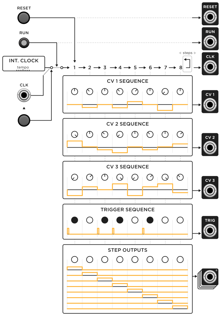
The module’s step position is advanced by either an internal or external clock. The TEMPO knob sets the rate of the internal clock and can be modulated with the TEMPO input. When the TEMPO CV attenuator knob is set to 100%, the tempo is adjusted by exactly 1V/octave. If a cable is patched into CLK, the internal clock is ignored, and the sequencer advances only when a clock trigger is received.
The STEPS knob sets the number of steps in the pattern. After the last step in the pattern is reached, an additional clock resets the step position to 1, and the RESET output emits a trigger. The step position can also be reset with the RESET button and trigger input.
The CV values and trigger states can be set for each step using the array of knobs and buttons. The row of STEP outputs indicates the current step position via a light and 10V gate signal. The CV 1, CV 2, CV 3, and TRIG outputs emit the values at the current step.
The RUN button and trigger input toggles the playback state. When not running, both internal and external triggers are ignored, so the step position does not advance. When the run state is toggled, the RUN output emits a trigger.
Multiple instances of VCV SEQ 3 can be synchronized by patching the STEPS, CLK, RUN, and RESET outputs of one instance into the corresponding inputs of another instance. The STEPS knob of the second instance must be set to 1 in order to set the correct number of steps.
Settings
Normally the TRIG output emits a 1 millisecond pulse when advancing to a step with an enabled trigger. Some hardware sequencers instead pass the external clock gate (however long it may be) through to the TRIG output if the step’s trigger is enabled. This behavior can be enabled by right-clicking the panel and clicking “Clock passthrough”. When using the internal clock with this mode enabled, the TRIG output emits a gate with a 50% duty cycle.
If needed, the pattern’s rows can be shifted left or right by right-clicking the panel and clicking “Rotate left” or “Rotate right”. As with most menu items in VCV Rack, you can hold Ctrl (Cmd on Mac) when clicking to keep the context menu open to rotate multiple times.