Gate logic processor
2.6.4
Author: VCV
License: GPL-3.0-or-later
Last updated:
Created:
Plugin: VCV Free
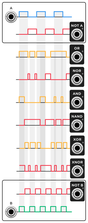
This gate processor applies Boolean logic operations to gate signals A and B.
In VCV Rack, a gate signal can be HIGH (usually 10V), representing an ON/TRUE state, or LOW (usually 0V), representing an OFF/FALSE state.
When the B button is pressed, the B signal is set to a HIGH state regardless of the B gate voltage.
-
The NOT A and NOT B outputs negate/invert the state of A and B, respectively. For example, NOT A is HIGH when A is LOW, and it is LOW when A is HIGH.
-
OR is HIGH when either A or B is HIGH, or both.
-
NOR is HIGH when neither A or B is HIGH.
-
AND is HIGH when both A and B are HIGH.
-
NAND is HIGH when A and B are not both HIGH.
-
XOR is HIGH when either A or B is HIGH, but not both.
-
XNOR is HIGH when both A and B are HIGH, or when neither are HIGH. In other words, XNOR is HIGH when the state of A is equal to the state of B.
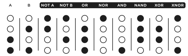
This information can be summarized in a truth table for all 4 possible input configurations of A and B. HIGH/true states are shown as a black circle ⬤, while LOW/false states are shown as a white circle ◯.
When two arbitrary gate signals A and B are combined with VCV Logic, the results can be several new but related gate signals, perfect for experimentation.